How do you do electrical drawings
Start with a collection of electrical symbols appropriate for your diagram.Draw circuits represented by lines.Drag and drop symbols to the circuits and connect them.Use line hops if any lines need to cross.
What do electrical drawings include?
- A site plan which shows the location of the building and any external wiring.
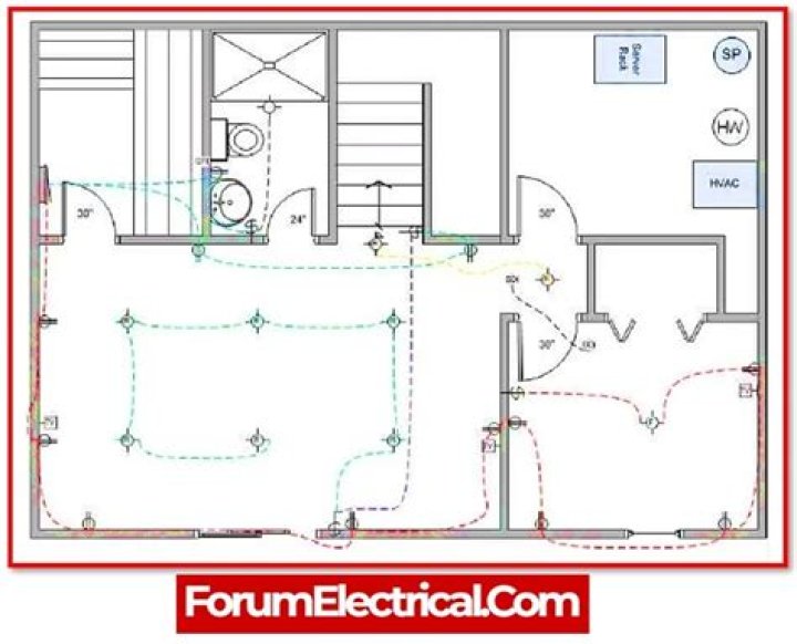
- Floor plans which show the positions of electrical systems on each floor.
- Wiring diagrams which show the physical connections and layout of electrical circuits.
What are electrical drawings called?
A circuit diagram (also known as an electrical diagram, elementary diagram, or electronic schematic) is a simplified conventional graphical representation of an electrical circuit. … The diagram does not show the physical arrangement of components.
What are the four main types of electrical drawings?
- Schematic Diagrams.
- Wiring diagrams.
- Block diagrams.
- Pictorial diagrams.
How do I plan an electrical outlet?
It is recommended to place an outlet in all four corners of the living room in addition to an outlet in the middle of each wall. Follow those recommendations, and there will be plenty of power for entertainment centers, extra lighting, and places to connect devices.
What type of wiring diagram is used in electrical plans?
Schematics Circuit Diagram One can easily troubleshoot certain schematic by applying electronic circuit theory. It is the most common type of electrical drawing and are mostly used in implementing electrical circuits by technician.
What are the 3 main functions of electrical drawings?
An electrical drawing is a type of technical drawing that shows information about power, lighting, and communication for an engineering or architectural project.
What is a one line electrical diagram?
The single-line diagram is the blueprint for electrical system analysis. … It shows a correct power distribution path from the incoming power source to each downstream load – including the ratings and sizes of each piece of electrical equipment, their circuit conductors, and their protective devices.What is a layout diagram electrical?
A drawing meant to depict the physical arrangement of the wires and the components they connect is called artwork or layout, physical design, or wiring diagram. Circuit diagrams are used for the design (circuit design), construction (such as PCB layout), and maintenance of electrical and electronic equipment.
What are the basic electrical symbols?- Ground or Earth. A ground symbol (IEC symbol 5017) identifies a ground terminal. …
- Resistor. A resistor reduces current flow. …
- Switch. Disconnects the current when open. …
- Capacitor. A capacitor symbol shows two terminals running into plates. …
- Fuse. …
- Antenna. …
- Inductor. …
- Transformer.
What are the 3 types of electricity?
There are three types of electricity – baseload, dispatchable, and variable.
Why do I need an electrical drawing?
Electrical drawings are absolutely crucial for documenting, troubleshooting, and communicating information about your power systems on your site. They can help to ensure your system runs smoothly, efficiently, and most importantly: safely.
How far should outlets be from the floor?
Standard Height for Outlet Boxes The standard height for wall outlet boxes is about 12 inches from the top of the floor covering to the bottom of the receptacle box (or 16 inches to the top of the box).
How do I choose a wall outlet?
- Step 1: Know if you need GFCI and AFCI outlets. Most electrical outlets in your home should have some sort of built-in safety device. …
- Step 2: Get the right outlet for your appliances and electronics. …
- Step 3: Know your existing wiring/circuits.
Where do you put receptacles?
The US National Electrical Code, Section 210.52, states that there should be an electrical outlet in every kitchen, bedroom, living room, family room, and any other room that has dedicated living space. They must be positioned at least every twelve feet measured along the floor line.
What is electrical design?
Electrical design is the process of planning and creating electrical equipment, such as electrical components, schematics, lighting equipment, power systems and telecommunications infrastructure.
What are the three diagram in electrical installation?
- Ladder or Line Diagram. Ladder or Line Diagram. A ladder or line diagram is a diagram that shows the function of an electrical circuit using electrical symbols. …
- Wiring Diagram. Wiring Diagram. …
- One-Line Diagram. One-line diagram or Single-line Diagram.
What are the 3 types of wiring diagrams?
There are three ways to show electrical circuits. They are wiring, schematic, and pictorial diagrams. The two most commonly used are the wiring diagram and the schematic diagram. The uses of these two types of diagrams are compared in Table 1.
What is the difference between a circuit diagram and a wiring diagram?
Wiring Diagram shows the actual practical connection between electrical appliances, components. Circuit Diagram just shows the simple connection between components it does not shows the practical connection.
What are layout drawings?
Layout Drawing. A layout drawing depicts design development requirements. It is similar to a detail, assembly, or installation drawing, except that it presents pictorial, notational, or dimensional data to the extent necessary to convey the design solution used in preparing other engineering drawings.
What are the five parts of a basic electrical circuit?
Electricity cannot flow without a power source (battery), and a load (bulb or resistor-electrical device/ component) and a closed conductive path (wires connecting it). Electrical circuits consist of wires, wire connectors, switches, circuit protection devices, relays, electrical loads, and grounds.
How do you read one line drawing?
When interpreting a single line diagram, you should always start at the top where the highest voltage is and work your way down to the lowest voltage. This helps to keep the voltages and their paths straight. To explain this easier, we have divided the single line into three sections.
What are the 6 most common symbols used for an electrical schematic diagram?
- Battery. The symbol for a battery is shown below. …
- Resistor. The schematic symbol of the resistor are drawn in two different ways. …
- Potentiometer. …
- Schematic Symbols of a Transistor. …
- Integrated Circuit. …
- Logic Gates. …
- Inductor. …
- Transformer.
How do you make a schematic diagram?
- Create the First Symbol. From (File > New) under Name: type Schematic. …
- Use the Pick tool to select both lines, and press Ctrl + D to duplicate them. …
- Right-click on the selected lines and select Symbol > New Symbol. …
- Add More Symbols. …
- Lay out the Symbols. …
- Connect the Circuit. …
- Add Text.
What do the symbols on a wiring diagram mean?
Thus in circuit diagrams and schematics, graphical symbols identify and represent electrical and electronic devices and show how they are electrically connected together while drawing lines between them represents the wires or component leads.