What is rotor current
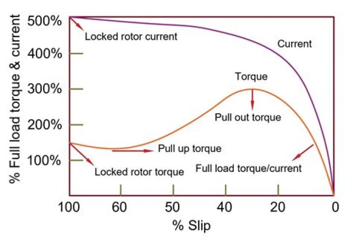
Locked rotor current is basically the current drawn by the motor at its rated voltage when its rotor is kept stationary or in other words rotor is not spinning or rotating. So when we start a motor, its rotor is already at rest. This means, starting current and locked rotor current should be same.
How is rotor current calculated?
i.e., Rotor current frequency = Fractional slip x Supply frequency (i) When the rotor is at standstill or stationary (i.e., s = 1), the frequency of rotor current is the same as that of supply frequency (f’ = sf = 1× f = f).
Is LRA the same as starting amps?
see less LRA – Locked Rotor Amps: The current you can expect under starting conditions when you apply full voltage. It occurs instantly during start up. RLA – Rated Load Amps: The maximum current a compressor should draw under any operating conditions.
What is rotor current in induction motor?
Within the induction motor, an electrical current in the rotor is induced by a varying magnetic field in the stator winding. The rotor current produces it’s own magnetic field, which then interacts with the stator field to produce torque and rotation.Why is locked rotor current high?
When the rotor is locked, the slip caused by the 3-phase stator coils is at it’s maximum, and it means that the voltage induced in the rotor coils (or bars) is also maximum. This maximum voltage causes the higher rotor currents.
What is the rotor frequency?
Rotor current frequency (fr) = (s)(f) The slip is negative when the rotor speed is more than the synchronous speed of the rotor field and is in the same direction. Calculation: Given, frequency (f) = 50 Hz. Slip (s) = 5 % = 0.05.
What is rotor EMF?
Rotor EMF. When the rotor is stationary, the 3-phase induction motor behaves as a 3-phase transformer with secondary winding short circuited. Thus, the per phase induced EMF in the rotor (or secondary) is given by, RotorEMF/Phase,𝐸2=𝐸1×𝑁2𝑁1=𝐾𝐸1…(
What is rotor and its types?
There are two types of induction motor rotors: Squirrel-cage rotor or simply cage rotor. Phase wound or wound rotors. The motors that use this type of rotor are known as Slip-ring rotors.What is the use of rotor?
Rotors are the moving part in an Alternator that have permanent magnets that move around the Stator’s iron plates to generate an Alternating Current (AC). Rotors require existing motion to function, so only once the engine or turbine is already running will a Rotor work with a Stator to provide a charge.
What is frequency of rotor EMF?The frequency of the induced emf in rotor is? Explanation: The induced frequency will be f = P(Ns-Nr)/2. f = 4(1500-1450)/2 = 100 Hz.
Article first time published onWhat's the difference between LRA and FLA?
FLA: Full-Load Amps: Amount of amperage drawn when motor is working at rated horsepower. … LRA: Lock-Rotor-Amps: A motor draws a surge of amperage when it starts to get the rotor rotating and to achieve the rated horsepower.
How do I know if my rotor is locked?
Out in the field, the rule of thumb for locked-rotor current is six times the full-load amperes marked on the motor’s nameplate. The result of multiplying the full-load amperes of a motor by six might be close to the actual locked-rotor current or the result might not be anywhere near the actual locked-rotor current.
What is LRA used for?
LRA or Lock Rotor Amps in its unabbreviated form is the current draw of a motor when the rotor is locked.
What is the difference between locked rotor current and starting current?
The term Locked rotor current usually used in blocked rotor condition. It is the current drawn by the motor when the load applied is heavier such that the motor stops rotation. The starting current is the initial current flow into the motor which is usually very high and controlled by using starters.
Is Locked rotor Amps the same as full load amps?
The locked rotor current is the measured current with the rotor locked and with rated voltage and frequency applied to the motor. The amount of current a motor can be expected to draw under full load (torque) conditions is called Full Load Amps.
What does FL Amps mean?
Full Load Amps, or F.L.A., represents the amount of current the motor is designed to draw at the rated horsepower. In the example nameplate, this means that when the motor is running under a full load at 230 volts, we can expect it to draw 5.4 amps. … In the example nameplate, the S.F.A. is eight amps at 230 volts.
What is rotor voltage?
Rotor bar voltage The rotating magnetic field induces a voltage in the rotor bars as it passes over them. This equation applies to induced voltage in the rotor bars. where: = induced voltage = magnetic field =conductor length =synchronous speed = conductor speed.
What is rotor reactance?
The rotor resistance R2 is constant. It is independent of slip. The reactance of the induction motor rotor depends upon the inductance of the rotor, voltage frequency, and rotor’s current. If L2 = inductance of rotor, the rotor reactance is given by. X2=2πf2 L2 But f2=sf1 ∴ X2=2π sf1 L2=s(2π f1 L2) Or X2=sX20.
What is the rotor frequency when the motor is standstill?
zero. 2f.
How is rotor EMF calculated?
The rotor emf at speed n depends on the difference in speed between the rotating field and the rotor: e = B · l · (vstator –vrotor ) = B · l · g · vstator = g · ( B · l · vstator ).
What is a rotor speed?
Rotor spinning Rotor speed depends, in part, on rotor diameter. Rotor speeds typically lie in the 120–210 m/s range, but mostly between 150 and 190 m/s, with a tendency to be higher with a smaller rotor diameter [6]. … A larger rotor diameter reduces the frequency of cleaning required to remove trash.
What is rotor slip?
“Slip” in an AC induction motor is defined as: As the speed of the rotor drops below the stator speed, or synchronous speed, the rotation rate of the magnetic field in the rotor increases, inducing more current in the rotor’s windings and creating more torque. Slip is required to produce torque.
What is a rotor in engineering?
The ARotor laboratory is a full scale rotor laboratory with facilities to measure rotors of up to 25,000 kg. … Beside the measurement applications, machining applications have also been developed, such as 3D grinding methods to compensate measured geometry errors in large flexible rotors such as paper machine rolls.
What is rotor assembly?
The rotor lamination assembly is heated homogeneously and brought to a set temperature. … Rotor Shaft Assembly. The rotor shaft is set into the rotor lamination stack using a delivery unit and then joined.
What are the parts of rotor?
The stator core, stator winding and the outer frame are the three parts of the stator whereas the rotor core and field winding are the parts of the rotor. The three-phase supply is given to the winding of the stator. The rotor is excited by the DC supply.
What is meant by plugging?
Plugging is the method of inducing negative torque in the rotor of an induction motor to rapidly bring its speed of rotation to zero. This is done by reversing the supply connection at the stator terminals.
What is back EMF in motor?
back EMF in Electrical Engineering Back EMF is the system in the coil of an electric motor that opposes the current flowing through the coil, when the armature rotates. When the speed varies, the winding characteristics may fluctuate, resulting in variation of back EMF.
What is the difference between rotor and motor?
As nouns the difference between rotor and motor is that rotor is a rotating part of a mechanical device, for example in an electric motor, generator, alternator or pump while motor is a machine or device that converts any form of energy into mechanical energy, or imparts motion.
What is the frequency of AC?
Frequency of Alternating current in India is 50 Hz. India has an AC supply of 50 Hz/ 220 volts. While the USA and many of the European countries have 60 Hz/110 volts supply.
What is the standard frequency of India?
The nominal frequency of operation in Indian grid is 50.0 Hz and the permissible frequency band specified by Indian Electricity Grid Code (IEGC) is 49.5 Hz to 50.2 Hz w.e.f 3rd May 2010.
Why rotor slots are skewed?
The rotor or stator slot of the induction motor skewed through some angle so that the bars lie under alternate harmonic poles of the same polarity or other words, bars must be skewed through two pitches. The main purpose of skewing is to reduce the magnetic logging between the starter and the rotor.